Overview
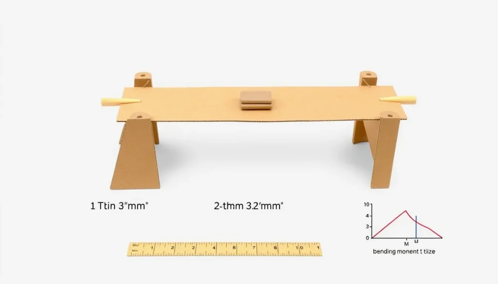
Cardboard is an everyday material that behaves like a lightweight wooden beam. When a bridge spans a gap, the material must resist bending (flexural) stresses caused by the weight placed on it. The thicker the cardboard, the larger its second moment of area, and the more load it can carry before it bends or crushes. This project lets children design, build, and test a simple beam bridge while systematically varying the cardboard thickness to see the effect on load‑bearing capacity.
Before You Begin
- Choose a well‑ventilated workspace with a sturdy table or desk.
- Adult supervision is needed for cutting cardboard, handling the scale, and ensuring safe lifting of weights.
- Gather all materials before you start; this reduces interruptions and keeps the test conditions consistent.
Materials
| Item | Quantity | Notes |
|---|---|---|
| Corrugated cardboard sheets | 3 | One thin (≈1 mm), one medium (≈2 mm), one thick (≈3 mm). Use the same flute type for all sheets for fairness. |
| Utility knife or scissors | 1 | Sharp blade for clean cuts. |
| Ruler or measuring tape | 1 | Accuracy to 1 mm. |
| Contact cement or strong craft glue | 1 bottle | Only a few drops per bridge; excess glue adds weight. |
| Wooden dowels or small metal rods | 4–6 | Serve as supports (spacers) at each end of the bridge. |
| Scale (kitchen or digital) | 1 | Measures added weight in grams. |
| Weights | Various | Sandbags, water bottles, or metal washers. Incremental steps of ~50 g work well. |
| Clamp or heavy books | 2 | Hold the bridge ends steady during testing. |
| Notebook, pen, and ruler | 1 set | Record observations and measurements. |
If corrugated cardboard of the exact thickness is unavailable, stack multiple single‑flute sheets to achieve the target thickness, being sure to keep the total thickness uniform across the test piece.
Design Constraints and Success Criteria
- Span: The bridge must span a 30 cm gap (approximately the width of an A4 sheet). This distance matches many classroom bridge challenges and keeps the test manageable.
- Length of bridge material: Use a single piece of cardboard no longer than 40 cm. This mirrors the limitation described in a first‑year civil engineering lab where students received one matboard sheet of 1016 mm × 813 mm × 1.27 mm (≈1.27 mm thick)【2】.
- Weight of the bridge itself: Minimize added glue; the bridge’s own weight should be less than 10 % of the total load you plan to test.
- Success criteria:
- Each bridge must hold the span without sagging more than 5 mm under its own weight.
- Record the maximum load (in grams) the bridge supports before a visible failure (crack, permanent bend, or collapse).
- Demonstrate a clear trend: thicker cardboard should support a higher maximum load.
Construction Steps
- Measure and cut the beam: Using a ruler, mark a 30 cm length on the cardboard sheet. Cut straight across with a utility knife. For consistency, cut all three thicknesses to the same length.
- Mark the cross‑section shape: A simple rectangular beam works, but you can improve stiffness by adding flanges (a thin “I‑beam” shape) drawn on the cardboard and cut out. Sketch the shape on the thin sheet first; use the same outline on the medium and thick sheets.
- Apply glue: Place a thin line of contact cement along the edges that will touch the supports. Press the beam onto the dowels (or rods) at each end, ensuring the beam is centered over the 30 cm gap. Hold for 30 seconds until the glue sets.
- Let it dry: Allow the glue to cure for at least 10 minutes. This ensures the bridge’s own weight does not shift during testing.
- Set up the test rig: Position two sturdy clamps or heavy books on a table, leaving a 30 cm gap between them. Place the bridge on the dowels so the ends rest on the clamps. Verify that the bridge is level and that the gap is exactly 30 cm.
Testing Procedure
- Zero the scale: Place the empty bridge on the scale (if the scale can hold the bridge) or record the bridge’s weight separately.
- Add weight incrementally: Place the first 50 g weight in the centre of the bridge span. Record the total load and note any visible deflection.
- Observe and record: After each addition, wait 5 seconds for the bridge to settle, then note:
- Deflection (measure with a ruler; record in mm).
- Any audible cracks or visual damage.
- Whether the bridge is still stable.
- Continue adding weight: Increase the load in 50 g steps until the bridge fails (breaks, collapses, or bends more than 10 mm). The load just before failure is the bridge’s maximum capacity.
- Repeat for each thickness: Disassemble the test rig, replace the bridge with the next thickness, and repeat steps 6‑10. Perform at least two trials per thickness to see consistency.
What to Observe or Measure
- Maximum load (grams): The highest weight the bridge supports before failure.
- Deflection at mid‑span (mm): How much the bridge sags under each load step.
- Failure mode: Does the cardboard crack, crush, or simply bend?
- Repeatability: Compare the two trials for each thickness; note any variation.
The Science Explained
When a load sits on a bridge, the material experiences two main stresses: bending stress on the top fibers (compression) and bottom fibers (tension), and shear stress along the depth. The resistance to bending is quantified by the second moment of area (I), which for a rectangular cross‑section is I = (b·h³)/12 (b = width, h = thickness). Because the thickness is cubed, even a small increase in h dramatically raises I, making the beam stiffer.
In practical terms, a 1 mm thick piece has an I value eight times smaller than a 2 mm piece of the same width, so it will bend much sooner under the same load. This relationship matches the observations made in university‑level cardboard bridge labs, where thin‑cardboard truss bridges showed significantly lower load capacities than thicker members【1】.

Cardboard also has a limited compressive strength. When the load becomes large enough, the corrugated core can buckle, especially if the outer skins are thin. Adding thickness not only raises I but also increases the distance between the compressive and tensile faces, delaying buckling. The failure modes you see—cracking of the outer skin versus crushing of the core—are direct consequences of these mechanics.
Troubleshooting
- Bridge slips off the supports: Ensure the dowels or rods are firmly glued and that the bridge ends are square to the supports.
- Excessive sag before any weight is added: Check that the cardboard is not already damaged; a small tear dramatically reduces stiffness.
- Uneven loading: Place the weight exactly in the centre of the span. Use a small piece of tape to mark the midpoint.
- Inconsistent results between trials: Make sure the glue layer is the same thickness each time; a thicker glue line adds unwanted material and can act as a weak spot.
Next Steps
After completing the three thickness tests, families can explore how other design changes affect strength. Examples include:
- Adding a second cardboard layer glued to the opposite side (making a sandwich beam).
- Changing the beam shape to an I‑section or a hollow tube.
- Replacing the corrugated core with a solid sheet of cardboard or a lightweight foam core.
These extensions deepen the investigation into how geometry and material distribution influence load capacity, echoing research on corrugated‑cardboard sandwich beams that used flax‑fiber skins for added strength【3】.
Related terms
- Second moment of area
- A geometric property of a beam’s cross‑section that describes how its area is distributed about a neutral axis; larger values mean the beam resists bending better.
- Bending stress
- The internal stress that develops in a material when it bends, causing compression on one side and tension on the other.
- Buckling
- A sudden failure mode where a compressive member (like the cardboard core) collapses sideways under load.
Sources & references
- Design–Build–Test in a First-Year Civil Engineering Laboratory: A Thin-Cardboard Truss Bridge Case Study, https://ascelibrary.org/doi/epdf/10.1061/JCEECD.EIENG-2550
- Artifact Four: Cardboard Bridge Design - Design Portfolio, https://jzabaladesignportfolio.weebly.com/artifact-four-cardboard-bridge-design.html
- Corrugated Cardboard Core Sandwich Beams with Bio-Based Flax Fiber, https://cdn.dal.ca/content/dam/dalhousie/pdf/faculty/engineering/research/research-chairs/crc-sustainable-infrastructure/2018McCrackenandSadeghian-CardboardManuscript.pdf